Interaction in 3D Graphics
Vol.32 No.4 November 1998
ACM SIGGRAPH
HMDs, Caves & Chameleon: A Human-Centric Analysis of Interaction in Virtual Space
Bill Buxton and George W. Fitzmaurice
Alias|Wavefront Inc.
Abstract
There are a various approaches to implementing virtual reality (VR) systems. The head mounted display (HMD) and Cave approaches are two of the best known. In this paper, we discuss such approaches from the perspective of the types of interaction that they afford. Our analysis looks at interaction from three perspectives: solo interaction, collaborative interaction in the same physical space and remote collaboration. From this analysis emerges a basic taxonomy that is intended to help systems designers make choices that better match their implementation with the needs of their application and users.Introduction
Immersive virtual reality (VR) was first suggested — as were so many other things — by Ivan Sutherland in 1965 [17]. Practical working systems have now been with us for over a decade and have been written about extensively (e.g., Rheingold, 1991) [15]. If one includes the early work of Krueger (1983) [11], they go back even further. The best known approach to VR is that of the head mounted display (HMD) coupled with head tracking. With such systems, one typically is presented with a stereo binocular view of the virtual world, often with stereo audio. By virtue of tracking the viewing position (the head) and orientation in the physical world, the view and perspective of the virtual are consistent with what one would experience in the physical world from the same actions.In addition to tracking viewpoint, which is tied to what is displayed to the user, such systems also typically permit some means of input, such as a dataglove [21] or some other high degree of freedom input to support interaction with the displayed virtual world.
As the art has progressed, alternative technical approaches to VR have emerged. Of these, we distinguish among three:
- Head mounted VR: systems as described briefly above, where one typically has a head mounted wide view stereo display coupled with head tracking, and some other means of input to support interaction.
- Cave based VR: where some or all of the walls of a room are rear-projection stereo displays. The user wears glasses to enable viewing the stereo images, and there is a head tracking mechanism to control what is projected (i.e., the view) depending on where the viewer is located and looking. In addition, there is some mechanism for interacting with what is seen.
- Chameleon type VR: which involves a handheld, or hand moved, display whose position and orientation are tracked in order to determine what appears on it. Furthermore, the display enables interaction with what it is showing.
VR, while expensive and still relatively new, is a powerful technology. It is being applied in a range of contexts ranging from entertainment to automotive design. But if one is going to engage the technology, then what path to follow, and why? What are the relevant dimensions? What are the pros and cons of each approach?
Providing some vocabulary and a framework in order to answer and address such questions is what motivates this brief discussion paper. After introducing each of the three classes of VR systems, we discuss them in terms of their ability to support three types of interaction:
- Solo: where there is only one person interacting in the virtual space.
- Same place collaboration: where there is more than one user interacting in the virtual space, but they are physically situated in the same location.
- Different place collaboration: where there is more than one user interacting in the virtual space, but they are situated in different physical locations.
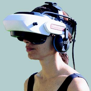
Figure 1: Modern inexpensive HMD: The General Reality CE-200W. (Photo: General Reality Corp.)
Head Mounted Display (HMD) VR
In HMD VR, the user “wears” a stereo display, much like a pair of glasses that provides a view into the virtual world. The physical form of these “glasses” can range from something on the scale of a motorcycle helmet to a pair of sunglasses. Figure 1 illustrates one example of a HMD.There is a great variety in display quality. The goal in the technology is to provide the widest field of view at the highest quality and with the least weight and at a reasonable cost. The reader is referred to Neale [12] for a reasonably up-to-date survey of HMD technology.
There exist a range of high degree of freedom (HDOF) input devices that can be used in interaction with such systems. An overall directory of sources to input devices can be found in Buxton [3]. Furthermore, a number of classes of HDOF technologies are discussed in the contribution of Shumin Zhai [20] in this special issue. Because of the typical mobility of the user (compared to desktop systems), however, most HMD systems use what Zhai calls a flying mouse class of device, often in conjunction with a dataglove type controller. In some cases, each hand is instrumented in order to support bimanual interaction.
The issue with virtually all HMDs is that the eyes are covered by the display. Consequently, one sees the virtual world at the expense of the physical one. Users cannot directly see their hands nor the devices that they are controlling. Similarly, they cannot directly see objects or other people who are in their immediate physical environment. Therefore, in order to function, some representation of such entities from the physical world must appear in the virtual one. In order to use my hands, I most likely must see a representation of them. Likewise, in order to avoid bumping into a table, I must see a representation of it, and to avoid bumping into you, I must see an avatar, or some other representation of you.
In collaborative work a significant observation that emerges from this is that, visually, HMD VR treats those in the same and those in remote physical spaces in the same way (some would say equally poorly, since visually there is no advantage to “being there” physically).
There is an important caveat to raise at this juncture. Some researchers have found a way around the problem of seeing the physical world (such as objects, their hands, tools or other people) while wearing HMDs. One approach is to mount one or more video cameras onto the HMD and feed the signals to the displays [19, 2, 16]. The cameras function as surrogate eyes providing a view into the physical world onto which is superimposed a computer generated view of the virtual world. The result is much like a head’s up display, and this approach to VR falls into the general category of augmented reality (AR), since it enables the computer to augment our view of the physical world with additional information. See [9] for an example of augmented reality and its application.
One important application of this technology is in remote collaboration. As an example, take the case of a technician who needs guidance to repair a complex piece of equipment from an expert who is not physically there. Through the cameras mounted on the technician’s HMD, the expert can remotely see what the technician is looking at. Conversely, using VR technology, the expert can point and indicate to the technician what to do. The guidance of the expert is superimposed on the technician’s view of the equipment in the HMD, thereby enabling the repair to proceed.
Clearly the ability to support AR is an important attribute of HMD VR. However, since it is not in the mainstream of HMD VR, in the bulk the discussion which follows we will assume that this is not in place.
Figure 2: Schematic showing the relationship among the eyes, hands and display in HMD Style VR.
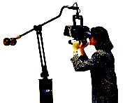
Figure 3: Fakespace BOOM3C boom mounted display (Photo: Fakespace,
Inc.)
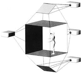
Figure 4: Schematic of an idealized Cave VR system. Tiled rear projection
stereo images appear on up to six faces of the room in which the operator
works. In practice, most Caves have three to four faces with projections.
(Image from: Cruz-Neira, Sandin, DeFanti, Kenyon and Hart, 1992).
Figure 5: Schematic showing relationship among the eyes, hands and
display in Cave style VR.
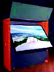
Figure 6: The ImmersaDesk VR System. A large format rear-projection
flat stereo display (Photo: Electronic Visualization Laboratory at the
University of Illinois at Chicago)
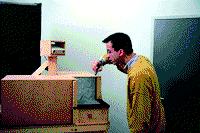
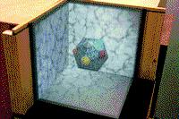
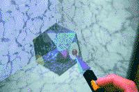
Figure 7: The Cubby System: A Small 3-Sided Cave [6, 7]
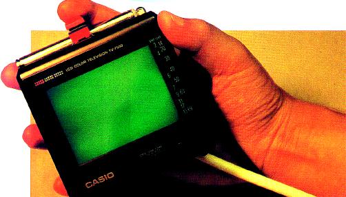
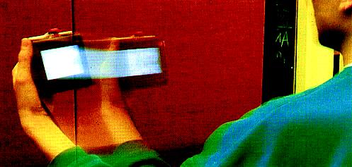
Figure 8: Chameleon Palm-held VR System. A monocular image is presented
on a palm-sized portable display. The display has position and orientation
tracking so what is displayed is determined by the display position. (It
is like a virtual magnifying glass). The display also incorporates some
manual controls. (Photo from Fitzmaurice, 1993)
Figure 9: Schematic showing relationship among the eyes, hands and
display in Chameleon style VR.
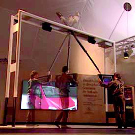
Figure 10: Art+Com virtual car display. This system is essentially
a larger format display version of Chameleon. A counter-balanced boom constrains
the display movement as well as supports its weight. (Photo: Art+Com).
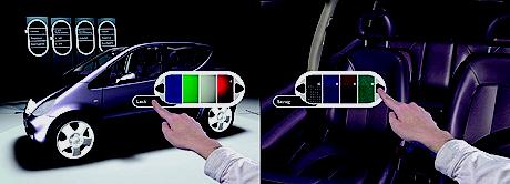
Figure 11: Art+Com VR Control: Note that the display in the previous
photo is a touch screen that enables the operator to interact with the
image. (Photo: Art+Com).
According to these criteria, and for the purposes of this paper, boom-mounted displays, such as illustrated in Figure 3, are a variation on HMDs, as opposed to a separate category (in contrast to the analysis of Cruz-Neira, Sandin, DeFanti, Kenyon and Hart, 1992) [4].
Caves
A significantly different approach to VR, called Cave VR, was introduced by Cruz-Neira, Sandin, DeFanti, Kenyon and Hart in 1992 [4]. In this class of VR, the user functions within a room on which one or more of the surfaces (walls, floor, ceiling …) is the display. An idealized representation of a Cave is shown in Figure 4. This shows four sides of a six-sided Cave. In a Cave, each of the displays is “tiled,” in that together they provide a seamless omni-directional view of the virtual scene. Furthermore, the displays are ideally stereo, and the operator views them through a set of lightweight transparent shutter glasses. The user’s head position is tracked within the Cave so that what is displayed preserves proper perspective, etc., in adapting to movements and change of location of gaze. That is, perceptually, the user sees the virtual scene in a manner consistent with if it were real. And, as anyone who has seen a stereo movie knows, the objects in the virtual scene do not just appear on the Cave walls and beyond. They can appear to enter into the physical space of the Cave itself, where the user can interact with them directly.As with HMD VR, manual interaction within the Cave is typically accomplished with a HDOF device such as a “flying mouse” (sometimes coupled with speech recognition), in order to enable the operator to remain mobile within the space.
One area where Caves differ from HMD VR is that, since the glasses are transparent, one can see the physical as well as the virtual world. Consequently, if you and I are both in the space, we can see each other as well as the virtual world. However, the way that we can share the scene has some distinct differences from HMD VR. Remember that what is displayed is determined by head tracking. If we are both in the Cave, we both are viewing the same displays, preventing us from each having our own “point of view.” (While we can both look at different things and different directions, we both do so as if from the perspective of the current location of the head tracker.) So the good news is, in the Cave we really are presented with the same view. The bad news is, you have to see it from my location, or vice versa.
In remote collaboration, where two Caves are linked, this constraint is softened since each Cave can have a unique view, but everyone within a single Cave must share the same one. But the advantage of being able to see each other in the context of the virtual scene is lost when collaborating across multiple Caves. In remote collaboration one must resort to the same techniques used in HMD VR — such as the use of avatars or some other representation — in order to see one’s remote collaborators within the virtual space.
Finally, there is one potential problem that is unique to same location collaboration in Caves. In the everyday world, you and I may find ourselves on opposite sides of an object of interest or discussion. But what happens in a Cave if the object of interest lies within the confines of the physical walls of the Cave? If we are facing each other in a Cave with a virtual object in between us, neither of us will be able to see the object as we are each blocking the screen on which it is being projected for the other person. Let us call this the “shadow effect.”
As with HMD VR, in Figure 5 we characterize Cave VR by means of a simple schematic. Here we illustrate that the eyes and hands are loosely coupled and mobile, and that the display is anchored in a fixed position. Furthermore, it shows that the head is tracked and that the hands are visible and located between the display and the eye.
Fitting into this characterization, are a number of other systems, which might therefore be considered “degenerate Caves.” One example would be large format projection displays such as the ImmersaDesk shown in Figure 6, developed at the Electronic Visualization Laboratory at the University of Illinois at Chicago (Czernuszenko, Pape, Sandin, DeFanti, Dawe and Brown, 1997) [5]. This is essentially a small one-sided Cave.
Another example would be what Ware and Booth [18] called fish tank VR. These are typically CRT systems which incorporate head-tracking, and present a perspective view (often not stereo), based on the user’s head position. Such systems can be thought of as very small format one-sided Caves (tunnels?) with a consequently limited field of view and range of mobility of the user.
Actually, small format caves have been built, showing that you don’t have to be able to walk around in a cave for the technology to be of value. The Cubby system developed at the Technical University of Delft in the Netherlands is one such example [6, 7].
Finally, flight and driving simulators, which involve a vehicle in a space (often only partially) surrounded by rear projection screens, would also fall into this category. The display is often not stereo, and it may not be flat. And the user is typically not mobile, being confined to the vehicle. However, the basic relationship among the view, hands and display are consistent with the Cave approach.
Chameleon Style VR
The third and least well known approach to VR that we will discuss was introduced by Fitzmaurice (1993) in his Chameleon system. This can be thought of as handheld VR. In the Chameleon system, the image appeared on a small display held in the palm of the hand. In this case, what appeared on the screen was determined by tracking the position of the display, rather than the head of the user.One way to think about the Chameleon approach is as a magnifying glass that looks onto a virtual scene, rather than the physical world. And while the display is small, and certainly does not give the wide angle view found with the Cave approach, the scene is easily browsed by moving the lightweight display, as shown in the bottom image of Figure 8.
This movement of the display actually takes advantage of a subtle but powerful effect in human visual perception. With respect to visual perception, Newton was wrong about the equivalence of relative motion. That is, moving a scene on a fixed display is not the same as moving a display over a stationary scene. The reason is rooted in the persistence of images on the retina, formally known as the “Parks Effect” [13]. Much like moving the cursor often leaves a visible trail on a screen, moving the Chameleon display across the field of vision, and updating the view with the motion, can leave an image of the larger scene on the retina. Hence, if the display can move, the effective size of the virtual display need not be the same as the physical size. (If you remain confused, think about the effect of drawing a pattern on a wall by quickly moving a laser pointer. Here, a whole pattern is displayed even though only one point is illuminated at any given time. The image is in your eye, not on the wall. Such is the human visual perceptual system, and Chameleon-like VR can take advantage of it.)
Interaction with this class of display tends to be based on devices such as buttons or (as seen in the next example) a touch screen coupled directly with the display. That is to say, the display device serves for both input and output. In no cases, to our knowledge, has stereo display been used with this class of system, although one can imagine achieving this using the same kind of shuttered glasses employed in Cave systems.
Like Cave systems, in Chameleon-like VR, one has an unobstructed view of people and objects in the physical world. However, unlike the Cave but as with HMD VR, in collaborating with others in the same physical space, each user has their own view. And yet, it is easy to have a mechanism for sharing a view without disorienting the other viewers, since orientation is mainly determined by one’s orientation in physical space. (Contrast this with switching views in either Cave or HMD VR.)
On the other hand, Chameleon VR shares the same problem as both HMD and Cave VR in establishing a sense of presence of others in collaboration involving different physical locations.
As with the other techniques, we can characterize Chameleon-like VR schematically. Figure 9 illustrates the tight coupling of the hand(s) with the display, as well as the tracking of the display, and the mobility (modulo any tethering) of all three.
There have been other examples that have taken the Chameleon-like approach. For our purposes, one of the most interesting was developed by Art+Com (1998) [1] to enable the public to view a virtual version of the new Daimler-Benz A-class vehicle at the IAA motor show in Frankfurt, September of 1997. This is illustrated in Figure 10.
In this example, the display was larger than in the original Chameleon system. Rather than handheld, it was supported by a counter-balanced boom. While mechanically not unlike the Fakespace boom seen previously in Figure 3, conceptually this system is quite distinct. It very much falls into the Chameleon-class of VR by virtue of the relationship of the hands to the display, and the user’s simultaneous visibility and awareness of the surrounding physical space.
In this example, the system was on a scale to enable the car to be viewed on a 1:1 scale. The user could walk through and view the virtual car with the help of a flat screen (LCD) attached to a swivel arm. What this example demonstrates is how the technology for interacting with the virtual space can be integrated seamlessly into the display. This is shown in Figure 11, which illustrates how a touch screen on the display was used to select things such as the color of the vehicle or fabric of the upholstery.
Finally, like HMDs, Chameleon-like systems have the ability to support augmented reality. In his paper, for example, Fitzmaurice [10] showed how location tracking not only told the device where it was physically, but also relative to other devices, or people. Brought close to a map, for example, it could give additional information about the region that it was close to. Or, brought beside a complex piece of machinery, by being aware of the fact, it could give valuable information about how to use or repair the device.
Some researchers, Rekimoto [14], for example, have augmented Chameleon-like devices further and added video cameras in a manner similar to those discussed in the section on HMDs. Using this approach, the computer-generated information can, likewise, be superimposed over a view of the physical world, with the same benefits discussed with HMDs.
Summary and Conclusions
We have surveyed three distinct approaches to VR. We have attempted to describe each in terms of properties that might influence their suitability for different types of applications. In particular, we have emphasized properties that emerge in different forms of collaboration. These are summarized in Table 1.Obviously, other factors will also affect what technology is adopted. Cost is always an issue. So is the question of the amount of space, and any specialized environments required. And even within type, there is a broad range of variation, in image quality, responsiveness, etc.
But in many cases, it may be that more global human factors are most important. By way of example, consider an automotive design studio that wants to use VR technology for design reviews. Cave technology can and has been used to good effect. However, the quality has to be balanced with the fact that there typically isn’t a Cave in every studio. Rather, the Cave is most commonly a shared resource in a different part of the building. It has to be booked and data transferred and set up. While this structure can support formal reviews, it does not lend itself to casual or spontaneous reviews by management, customers or designers. That is to say, social issues might be the determining factor in choosing something like a Chameleon VR system, even if the fidelity does not match that of the alternative approaches.
VR technologies are expensive and not well understood. In our opinion, there is no “right approach” without a careful analysis of user, task and context (physical and social). Hopefully, the concepts outlined in this paper make some progress in paving the path to an understanding of the issues that will support such decisions. In the meantime, the authors welcome comments, suggestions and questions.